| | | | | | | | Arbiter Fuzz Face
Welcome to a legend. The Dallas-Arbiter Fuzz Face has been around since 1966, and it shows no signs of dying any time soon. Through this design's past you'll detect all kinds of different variations in the basic original circuit, from PNP Germanium to NPN Silicon, and a countless number of fuzz pedals that are based on information technology. 1 of the about notable Fuzz Face-based baloney pedals is my personal favorite...the Sola Audio ToneBender MKII. The Fuzz Face has been played past about every famous guitar player that has ever lived, and this tendency will most likely continue for a very long hereafter. |
I think that this pedal's longevity is due in office to its very simple design. There are four resistors, iii capacitors, two potentiometers, and two transistors...that's it. The original resistors were 1/2-watt carbon-limerick with a tolerance of �x%. The input capacitor was a 2.2�F electrolytic axial lead. The capacitor from the wiper lug of the fuzz pot to ground was a twenty�F electrolytic with axial leads. The 0.01�F capacitor that connected to the third lug of the book pot was metallized polyester. The original versions of the Fuzz Face were equipped with PNP Germanium transistors. In that location were at to the lowest degree iii types used: NKT275, AC128, and SFT363E. These three transistors are quite difficult to come up by these days. Beware of modern-day reproductions of the AC128 and NKT275. As for the SFT363E...I've never even seen one! The excursion board beneath has NKT275 transistors. 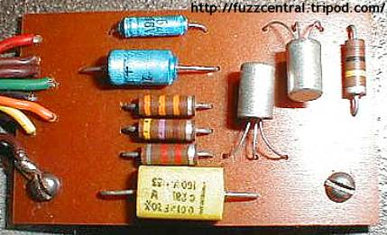 Here's a schematic of the original Germanium transistor version of the Dallas-Arbiter Fuzz Face up:  |
Every bit fourth dimension wore on, Germanium transistors were slowly being phased out in favor of the more stable and consequent Silicon versions. Equally a outcome, Dallas-Arbiter began equipping the Fuzz Face pedals with these new transistors with differing results. They do audio different from the original Germanium versions, usually with a more harsh and aggressive clipping equally opposed to the "soft" clipping characteristics of Germanium. At that place was only 1 part that was changed in the excursion other than the transistors. The 470-ohm resistor was replaced with a 330-ohm. Also, accept a expect at the picture of the Silicon Fuzz Face circuit board beneath. Notice that the position of the 33K and the 330 resistors are opposite of what they are in the Germanium version. The 470 was in the centre in the previous version, but now it's moved to the outside next to the 20�F capacitor. The transistors that were used in these versions included: BC108C, BC183L, BC109, BC109C, and BC209C. Almost, if not all, of these transistors are withal beingness produced and are readily bachelor. A while back I ordered some BC108 and BC109C from Futurlec, but I don't recommend them equally a supplier because of their painfully slow shipping. The circuit lath beneath has BC183L transistors, which have the B-C-E pinout. All the other transistors that were used take the more standard C-B-East pinout, so if you run beyond a Fuzz Face up with something other than the BC183L, the base and collector leads volition be twisted around to work properly. 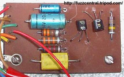 Here'southward a schematic of the last of the original Dallas-Arbiter Fuzz Faces, the NPN Silicon:  |
In contempo years at that place has been a huge resurgence of interest in the original Czar Fuzz Faces, probably fueled by the very mediocre sounding Dunlop Fuzz Faces. A couple of years back, the Arbiter visitor made a limited run of reissue Fuzz Faces, complete with AC128 transistors. If yous have a look at the circuit lath picture and the schematic below, you lot'll run across that information technology'southward not exactly a reissue, but an improved version of the original. Still, all the reissue circuits aren't the aforementioned from unit to unit of measurement...there are quite a few variations in the circuit...mostly with the two collector resistors on the two AC128 Germanium transistors and the output capacitor. Below the circuit board pic y'all'll see the schematics of two different variations of the reissue circuit...only there are more! 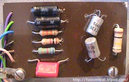 Hither'south the schematics of a couple of the variations of the Czar Fuzz Confront Reissue, with changes highlighted in red:   |
Information technology's incommunicable to draw a conclusion as to which version is "meliorate" than the other, because some people like the Silicon versions, and some people don't. It is safe to say, nonetheless, that the Silicon versions will obviously be free of one major problem that plagued the Germanium Fuzz Faces...temperature instability. Information technology's been noted many times over that if they get likewise hot...they'll stop working. Information technology was also much easier to produce more consequent sounds from unit to unit of measurement with the Silicon versions (whether those "sounds" were good or non was left for the purchaser of pedal to determine). A problem with Silicon transistors that doesn't seem to exist with Germanium is that they can have too much proceeds. Too much gain will crusade a Fuzz Face up to sound horrid. With Silicon it becomes very hard to stick with the Q1 hfe of 70 and Q2 hfe of 120, because most Silicon transistors are way over 120 to brainstorm with. Someone in Aron's Stompbox Forum said that placing a 100pF capacitor beyond the Collector-Base junction of the transistors in a Silicon Fuzz Face clone would help control the proceeds and oscillation, so if y'all decide to build this version, keep that in mind. |
I personally exercise not call up that wiring up PNP transistors (Silicon or Germanium) as negative ground is ane of the all-time ideas. The PNP transistors are but not meant to function with a negative ground and osciallation and "motorboating" sounds are common results of wiring a Fuzz Face with PNP transistors as such. Hither's some more information from R.G. Keen (GEOFEX): While in theory, the negative footing conversion for FF and other PNP circuits ought to work every time, there are a significant number of times where information technology causes oscillation, motorboating, etc. Sometimes you can make clean this up past putting a big freaking capacitor across the ability leads, sometimes you likewise need a low-impedance 0.i�F ceramic, likewise, and sometimes you need divine intervention. Try it if yous want, just be aware that there are weather and layouts that will non be trouble gratis if you flip power and ground. And then, in my stance, I would always leave PNP transistor-equipped circuits as positive footing. A circuit like the Fuzz Face will use such a small amount of current that a bombardment will last a very long time, even with heavy utilize...as long equally at that place's not an LED to increment electric current draw. If you're absolutely determined to use a negative ground Fuzz Face, I would suggest that you become through the actress trouble of getting some NPN Germanium transistors which will work properly with a positive ability supply and negative ground. Small Bear Electronics has NPN Germanium transistors. |
There has been a lot of controversy about the value of using carbon composition resistors in a circuit when you're trying to clone the sound of a vintage effect pedal. Merely for my Fuzz Face up clone, I've decided to build information technology equally accurately as possible, which means using every bit many NOS parts as I tin can become my hands on, and when they're non available, using new production parts that can reproduce the values of the originals. The 1/ii-watt carbon comp. resistors are bachelor from Mouser, although these are 5% tolerance instead of the 10% that the original circuit used, just this simply means that the value of the resistors will be closer to the desired resistance. I too had quite a time finding 20�F axial pb electrolytics, simply afterwards looking through the Mouser itemize, I discovered that they do indeed stock 20�F/25V Sprague Atom capacitors, which will be perfect. For the 0.01uF capacitor I'll be using an original-type flat, metallized polyester moving-picture show with axial leads. Locating the right transistors for this excursion could also prove to be a problem, but luckily I take some SK-series Germanium transistors that are but right. I likewise soldered a 2M2 input pulldown resistor to the underside of the circuit board to forbid it from popping with true bypass. |  | 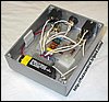 | 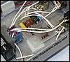 |
Annotation: These files are NOT to exist used in a pedal that you lot are building for profit. The PCB file is copyrighted artwork and is subject to a licensing fee. Dallas-Arbiter Fuzz Face PCB
| Here
| Dallas-Arbiter Fuzz Face Layout
| Here
| Dallas-Arbiter Fuzz Face Parts List
| Here
| Build Difficulty: Easy
| 
|
|
The new Fuzz Face PCB and Layout that I take drawn is based on the Axis Face excursion board, which is quite maybe the smallest and most compact Fuzz Face excursion board available. The layout besides uses a 10K trimpot on the collector of Q2 and then that that biasing can be adapted precisely...around -4.5VDC to -5VDC. It also features a 2.2M input pull-downward resistor to prevent "true bypass pop", a 100uF power supply filtering capacitor and a 1N4001 contrary polarity protection diode to assist protect the circuit from accidental reverse polarity power supply connections. This PCB and Layout tin can be used to build PNP or NPN transistor versions. Just remember that if y'all're edifice NPN Silicon the 470-ohm resistor should be replaced with a 330-ohm resistor, and you'll have to opposite the polarity of the two eletrolytic capacitors and it will need to be fed +9VDC instead of -9VDC.
| | | | | | |
|
0 Response to "Just Had a Capacitor Replaced on My Ac Compressor"
Post a Comment